End-Winding Tests
Modal testing for stator end-windings: extend the reliability of your assets!
End-winding tests are essential for evaluating the structural integrity and performance of stator windings in large electrical machines. They are invaluable tools in both manufacturing and maintenance contexts.
End-winding testing is governed by the standard IEC TS 60034-32:2016, which provides detailed guidelines for conducting thorough assessments to ensure reliability. This standard introduces two key techniques:
Driving Point Analysis (DPA)
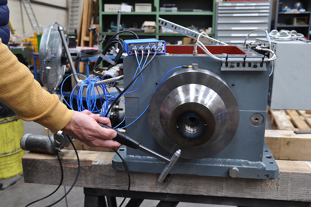
DPA measures the vibrational behavior of each individual stator end-winding, excited by an impact hammer. This method enables the detection of potential issues by checking for eigenmodes in the vicinity of electrical harmonics #1 and #2.
Experimental Modal Analysis (EMA)
EMA verifies the natural frequencies and mode shapes of electrical machines globally, aiming to mitigate heightened vibration levels. It involves measuring transfer functions and identifying dynamic properties through impact tests and accelerometers. It is crucial that global modes are kept clear of electromagnetic field harmonics.
Generator Stator Endwinding Bump Test
with OROS noise and vibration analyzer
Generator Overhauling
Why choosing OROS End-Winding solution?

Teamwork instruments
4-32 channels portable, flexible and rugged systems, made for the field with high-end metrology capabilities.

Guided by a sequencer
An Excel-configurable sequential guidance tool makes it easy to measure end-winding numbers, track progress, and redo measurements as needed.

Smart marker
Works in real-time on every new FRF. Advanced algorithm extracts amplitude, phase, and damping of each peak in frequency ranges near electrical harmonics, providing precise insights effortlessly.

Auto-reporting
Easily export vital data provided by Max Marker to your pre-defined reports in Word & Excel. This seamless export occurs after each measurement or during post-processing.

Data check tool
Featuring algorithms for automatic detection of double impacts and overloaded signals. It also offers a manual mode for sensitive test conditions.

Circular mode shape animation
Visualize deformations experienced by the generator at resonant frequencies, enhancing understanding and analysis.

Modes identification
In addition to the Narband method (peak-picking), the Broband method offers CMIF and Stability Diagram. Based on the frequency domain p-LSCF method, data can be curve-fitted to extract modal parameters.


